


We have deployed and opened to public external use a small version of what will grow into a large mobile robotic wireless testbed. The small version (6 Motes and 6 Stargates on 6 robots, all remotely controllable, plus 25 static Motes) is in an open area within our offices; the big one will be elsewhere.
This manual is broken up into the following sections:
If you are interested in how the mobile testbed works, you can read the following paper (to appear at IEEE Infocom, April 2006):
Mobile Emulab: A Robotic Wireless and Sensor Network Testbed
You can read a shorter overview of the mobile testbed in this article:
Real Mobility, Real Wireless: A New Kind of Testbed
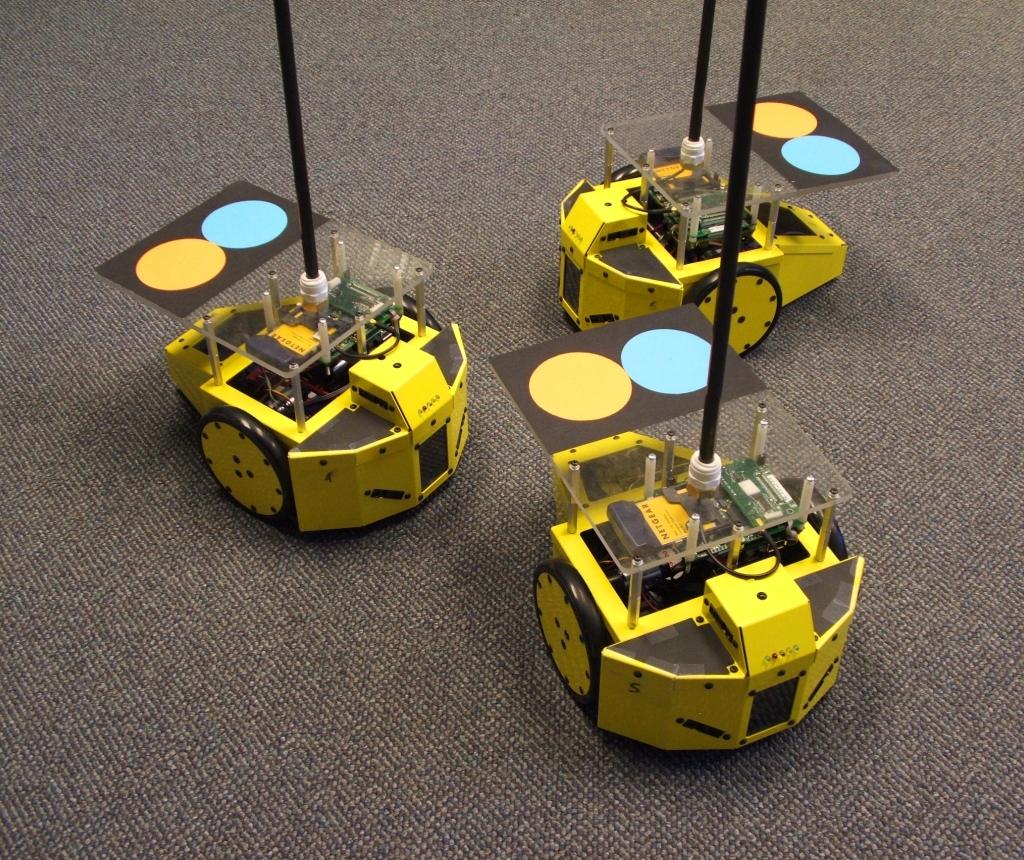
In addition to fixed wireless nodes (currently predominantly 802.11), Emulab also features wireless nodes attached to robots that can move around a small area. These robots consist of a small body (shown on the right) with an Intel Stargate that hosts a mote with a wireless network interface. The goal of this "mobile wireless testbed" is to give users an opportunity to conduct experiments with wireless nodes that are truly mobile. For example, mobile nodes could be used to realistically test and evaluate an ad-hoc routing algorithm in a fairly repeatable manner. This document is intended as a tutorial for those interested in making use of this testbed; there is also a short reference manual available that gives a few details about the workings of the system.
The current features of the mobile wireless testbed are:
Due to the "brand-new" nature of this part of Emulab, there are some limitations you should be aware of:
Creating a mobile wireless experiment is very similar to creating a regular Emulab experiment: you construct an NS file, swap in the experiment, and then you can log into the nodes to run your programs. There are, of course, some extra commands and settings that pertain to the physical manifestations of the robots. This tutorial will take you through the process of: creating a mobile experiment, moving the robots to various destinations, creating random motion scenarios, and "attaching" transmitter and receiver motes to the robots in your experiment.
set ns [new Simulator]
source tb_compat.tcl

set topo [new Topography]
$topo load_area MEB-ROBOTS

$ns node-config -topography $topo

set node(0) [$ns node]

$node(0) set X_ 3.01
$node(0) set Y_ 2.49

$ns run
Figure 1: Example NS file with mobile nodes.
Some parts of that example should be familiar to regular experimenters, so we will focus mainly on the new bits of code. First, we specified the physical area where the robots will be roaming by creating a "topography" object and loading it with the dimensions of that area:
In this case, the "MEB-ROBOTS" area is the name given to part of our office space in the Merrill Engineering Building. Next, we change the default node configuration so any subsequent calls to "Line 4: set topo [new Topography] Line 5: $topo load_area MEB-ROBOTS
[$ns node]" will
automatically attach the node to the topography we just created:
Finally, after creating the robot, we need to set the initial position in the area:Line 7: $ns node-config -topography $topo
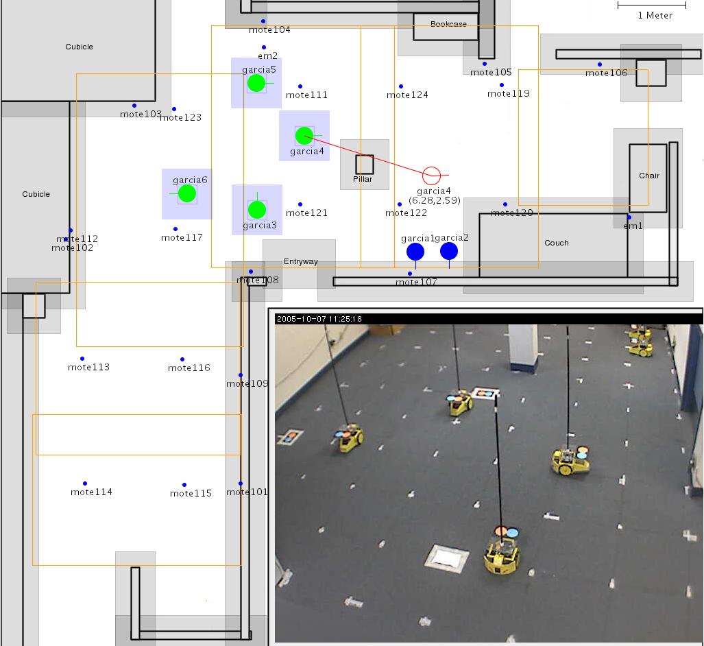
The values specified above are measured in meters and based on the map located here, where the origin is in the upper left hand corner, with positive X going right and positive Y going down. You can also click on the map to get a specific set of coordinates. Note that any coordinates you specify must not fall inside an obstacle, or they will be rejected by the system. A Java applet that updates in real time is linked from the above page, or can be accessed directly here.Line 11: $node set X_ 3.01 Line 12: $node set Y_ 2.49
With this NS file you can now create your first mobile experiment. Actually creating the experiment is the same as any other, except you might want to check the "Do Not Swapin" checkbox so that the creation does not fail if someone else is using the mobile testbed at the time. Once the area is free for use, you can swap-in your experiment and begin to work.
Now that you have a node allocated, let's make it mobile. During swap-in, Emulab will start moving the node to its initial position. You can watch its progress by using the "Robot Map" menu item on the experiment page and checking out the webcams or the applet version of the map that updates in real time.
 |
 |
Take a few moments to familiarize yourself with those pages since we'll be
making use of them during the rest of the tutorial. One important item to note
on the robot map page is the "Elapsed event time" value, which displays how
much time has elapsed since the robots have reached their initial positions.
The elapsed time is also connected to when "$ns at" events in the
NS file are run. In this case, there were no events in the NS file, so we'll
be moving the robot by sending dynamic SETDEST events, much like sending START
and STOP events to traffic
generators and program
objects.
Once the robot has reached its initial position, lets move it up a meter. To
do this, you will need to log in to ops.emulab.net and run:
1 ops:~> /usr/testbed/bin/tevc -e proj/exp \
         now node-0 SETDEST X=3.0 Y=1.5
Figure 2: Command to send an event that will move the robot to
the coordinates (3.0, 1.5). Don't forget to change proj/exp to
match your project and experiment IDs.
Then, check back with the map and webcams to see the results of your handiwork. Try moving it around a few more times to get a feel for how things work and where the robot can go. Note that the robot should automatically navigate around obstacles in the area, like the pole in the middle, so you do not have to plot your own course around them.
In addition to driving the robot with dynamic events, you can specify a static
set of events in the NS file. For example, you can issue the same move as
above at T +5 seconds by adding:
$ns at 5.0 "$node(0) setdest 3.01 1.5 0.1"
Figure 3: NS syntax that moves the robot to the same
destination as in Figure 2.
Note that "setdest" takes a third argument, the speed, in addition to the X and Y coordinates. The robot's speed is currently fixed at 0.1 meters per second.
Generating destination points for nodes can become quite a tedious task, so we provide a modified version of the NS-2 "setdest" tool that will produce a valid set of destination points for a given area. The tool, called "tbsetdest", is installed on ops and takes the following arguments:
Now, taking your existing NS file, we'll add another node to make things more interesting:
- -n nodes - The total number of nodes to generate motion for. The format for the node variables in the generated code is, "
$node(N)", so write your NS file accordingly.- -t secs - The simulation time, in seconds.
- -a area - The name of the area where the robots will be roaming around. Currently, MEB-ROBOTS is the only area available.
...
$ns node-config -topography $topo

set node(0) [$ns node]
set node(1) [$ns node]
Figure 4: Excerpt of the original NS file with an additional
node.
Then, use "tbsetdest" to produce some random motion for both robots:
Here is some sample output from the tool:2 ops:~> /usr/testbed/bin/tbsetdest -n 2 -t 60 -a MEB-ROBOTS
$node(0) set X_ 3.01
$node(0) set Y_ 2.49
$node(1) set X_ 1.22
$node(1) set Y_ 3.61
set rtl [$ns event-timeline]
#
# nodes: 2, pause: 0.50, max x: 5.90, max y: 4.00
#
$rtl at 0.50 "$node(0) setdest 0.92 3.28 0.10"
$rtl at 0.50 "$node(1) setdest 0.61 3.02 0.10"
$rtl at 9.50 "$node(1) setdest 0.88 2.09 0.10"
$rtl at 19.64 "$node(1) setdest 2.80 2.07 0.10"
$rtl at 23.37 "$node(0) setdest 5.62 2.79 0.10"
$rtl at 39.43 "$node(1) setdest 4.98 1.65 0.10"
#
# Destination Unreachables: 0
#
Figure 5: Sample "tbsetdest" output.
You can then add the second node and motion events by clicking on the "Modify Experiment" menu item on the experiment web page and:
$ns run" command; and
These commands create a new "timeline" object and then add events to it, much like adding events using "Line 5: set rtl [$ns event-timeline] Lines 9+: $rtl at ...
$ns at". The difference is that the
events attached to a timeline object can be requeued by sending a START event
to the timeline, in contrast to the "$ns at" events which are only
queued when the event system starts up. This feature can be useful for testing
your experiment by just (re)queueing subsets of events.
Once the modify completes, wait for the robots to reach their initial position
and then start the robots on their way by running the following on ops:
3 ops:~> /usr/testbed/bin/tevc -e proj/exp now rtl START
Figure 6: Command to start the "rtl" timeline. Again, don't forget to change proj/exp to match your project and experiment IDs.
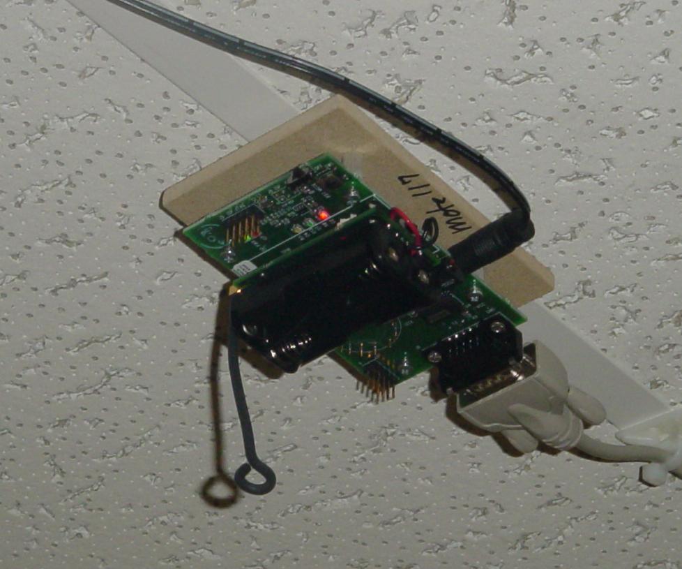
Now that you are getting the hang of the mobility part of this testbed, we can move on to working with wireless network traffic. As stated earlier, each of the robots carries a Mica2 mote (pictured on the right), which is a popular device used in wireless sensor networks. We'll be using the motes on the mobile nodes you already have allocated and loading them with TinyOS demo kernels, one that will be sending traffic and the other receiving.
## BEGIN mote nodes
$ns node-config -topography ""

set receiver [$ns node]
tb-set-hardware $receiver mica2
tb-set-node-os $receiver TinyOS-RfmLed
tb-fix-node $receiver $node(0)

set transmitter [$ns node]
tb-set-hardware $transmitter mica2
tb-set-node-os $transmitter TinyOS-CntRfm
tb-fix-node $transmitter $node(1)
## END mote nodes
Figure 7: NS syntax used to "attach" motes to a robot.
This code creates two mote nodes and "attaches" each of them to one of the mobile nodes. The OSs to be loaded on the mote nodes are the receiver, TinyOS-RfmLed, and the transmitter, TinyOS-CntRfm. These are standard TinyOS kernels supplied by Emulab; uploading your own is covered below. The receiver kernel will listen for packets containing a number from the transmitter and display the number, in binary, on the mote's builtin LEDs. The transmitter kernel will then send packets every second containing the value of a counter that goes from one to eight. So, if the mote's radios are well within range of each other, the receiver should pick up the packets and display the number on the LEDs. Of course, since you're not physically around to see that, you can click on the "Show Blinky Lights" menu item on the experiment web page to bring up a webpage with an applet that provides a near real-time view of the lights.
After the modify completes, try moving the nodes close to one another and far away, to see the lights updating, or not. You should also try running the nodes through the random motion created earlier and watching for the same effect on the lights.
## BEGIN fixed mote nodes
set fixed-receiver [$ns node]
tb-set-hardware $fixed-receiver static-mica2
tb-set-node-os $fixed-receiver TinyOS-RfmLed
## END fixed mote nodes
Figure 8: NS syntax used to add a fixed mote.
This code creates a single mote and loads the same TinyOS image as was
previously loaded onto the mobile receiver mote. Since the fixed
motes are mounted on serial programming boards, you will not be able to access
their LEDs as you did when adding mobile motes.
If you want to choose a specific mote from the topology (view placement and
positions by looking at the robot map), add the
following NS code:
tb-fix-node $fixed-receiver mote107
Figure 9: NS syntax used to select a specific fixed mote.
This code allows you to explicitly choose mote107, rather than allowing Emulab to select a mote on your behalf. Those who require very specific wireless network topologies may wish to use this command.
You can use the WSN Connectivity Applet to choose specific motes with desired link quality. Then, using the mechanism above, you can bind the specific mote you want to a node name in your experiment.
make mica2'). Then, upload the binary that gets
placed in build/mica2/main.srec to our
mote image
creation page. This page will ask you for a 'descriptor'. This
descriptor can then be used in tb-set-node-os lines in your
NS files, and your app will be automatically loaded on the appropriate mote(s).
Alternatively, if you don't have a local TinyOS build environment, just load
ours onto an Emulab PC in your experiment. You can do this by setting the node
operating system to RHL90-TINYOS using the tb-set-node-os
command (as shown in the Emulab tutorial). This image is based off Emulab's
default RedHat 9.0 image and has an installation of a TinyOS 1.1.14 CVS
snapshot. When you log in to the node, the $TOSROOT and $TOSDIR environment
variables will be set to /opt/tinyos-1.x and /opt/tinyos-1.x/tos,
respectively. Your $CLASSPATH variable will also include the TinyOS Java paths
necessary to run many common Java applications supplied with TinyOS.
Also, at the current time, all
of our motes have radios in the 900MHz band, so see the TinyOS
CC1000
radio document to make sure you're tuning the radios to the right band.
When you inevitably make changes to your code, you can simply place the new kernel in the path that was automatically constructed for you by the image creation page; the next time you use that OS in an NS file, the new version will be loaded. If you'd like to load your node code onto your motes without starting a new experiment, you have two options:
os_load allows you to load an kernel that has already been
defined as an image, as above. You give it the image descriptor with its
-i argument, and you can either give the physical names of all
motes you want to reload, or a -e pid,eid argument to reload
all nodes in the given experiment.
tbuisp allows you to load a file directly onto your motes
without having to register it as an image. This can be a quick way to do
development/debugging. Just pass it the operation upload, the
path to the file you wish to load, and the physical names of your motes.
Both of these are commands in /usr/testbed/bin on ops.emulab.net. They are also available through our XML-RPC interface, so you can run them from your desktop machine to save time - the file given as an argument to tbuisp is sent with the XML-RPC, so you don't need to copy it onto our servers.
To facilitate mote interaction, logging, and evaluation, we provide easy
access to each mote's serial programming board's serial interface. By simply
adding a PC node to your experiment, and adding some NS code, you can
access each mote's serial port directly on that PC. To access
mote107's serial interface, add the following NS code to your
experiment:
## BEGIN adding mote serial line access
set manager [$ns node]
tb-set-node-os $manager RHL-TINYOS

$ns connect [$fixed-receiver console] $manager
##END adding mote serial line access
Figure 10: Accessing mote serial interface.
This code allocates a single PC, manager, which runs our
manager PC, where it
is available as a pseudo tty device. You can read and write to the ptty
normally, except that some hardware-specific ioctl() syscalls may fail (this
happens because you are not working with the physical serial port). The pseudo
tty will be available on your manager node as
/dev/tip/MOTE_NAME (in this case,
/dev/tip/fixed-receiver). You can access other mote serial
interfaces by duplicating the above code, and changing the mote variable. If
the software you are using to access the mote's serial interface insists on
using /dev/ttyS1 or similar, you can simply run the following command on
your manager PC:
sudo rm /dev/ttyS1 && sudo ln -s /dev/tip/fixed-receiver /dev/ttyS1
Figure 11: Easing the pain for applications that use a specific
serial device.
If you need to use /dev/ttyS0 on our RHL-TINYOS images, you may remove and relink the device as shown in Fig. 11, but background monitor scripts may decide to restart the serial port getty. This will remove your link. However, you should only need to relink /dev/ttyS0 when you restart your program.


